Introduction #
Deye, Sunsynk and Sol-Ark inverters can be connected to the Qilowatt system using a Modbus module. This guide explains the necessary settings, wiring connections, and how to start the module.
Prerequisites #
• A technician has verified that the inverter is operating correctly
• The inverter is able to charge batteries from the grid and, if permitted, sell energy back to the grid
• Battery maximum power limits are taken into account
• A Modbus R1 or R2 module is available
• Required tools and a communication cable (CAT5 or CAT6)
• The inverter is able to charge batteries from the grid and, if permitted, sell energy back to the grid
• Battery maximum power limits are taken into account
• A Modbus R1 or R2 module is available
• Required tools and a communication cable (CAT5 or CAT6)
Step-by-step Guide #
Inverter settings #
1. Open Deye inverter menu.
2. Configure the following settings:
• Modbus SN (address): 01
• Master/Slave: Slave
• Modbus baudrate: 9600
• Time of Use: activated
2. Configure the following settings:
• Modbus SN (address): 01
• Master/Slave: Slave
• Modbus baudrate: 9600
• Time of Use: activated
Installing the module #
1. Install the MODBUS module according to the installation manual.
2. Connect the communication cable (CAT5 or CAT6) from the module’s RS485 A and B terminals to the corresponding inverter port.
⚠️ Important!
• If the inverter mainboard has a DRM port:
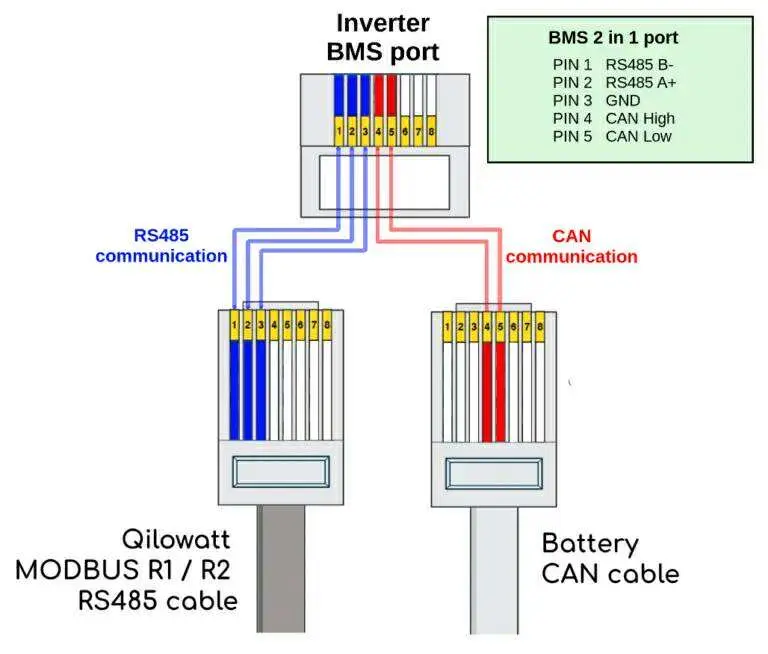
Connect the MODBUS R2 module terminals A and B to the inverter BMS port pins:
• Pin 1 → B+
• Pin 2 → A-
If the BMS port is already in use by the battery, use the Y-splitter included in the installation kit.
• If the inverter does not have a DRM port:
Connect the MODBUS R2 module terminals A and B to the inverter Modbus port pins:
• Pin 7 → A-
• Pin 8 → B+
2. Connect the communication cable (CAT5 or CAT6) from the module’s RS485 A and B terminals to the corresponding inverter port.
⚠️ Important!
• If the inverter mainboard has a DRM port:
Connect the MODBUS R2 module terminals A and B to the inverter BMS port pins:
• Pin 1 → B+
• Pin 2 → A-
If the BMS port is already in use by the battery, use the Y-splitter included in the installation kit.
• If the inverter does not have a DRM port:
Connect the MODBUS R2 module terminals A and B to the inverter Modbus port pins:
• Pin 7 → A-
• Pin 8 → B+
Starting the module #
1. Switch on the circuit breaker of the MODBUS R1 / R2 module (or insert the fuse).
2. Check if the module’s white LED indicator starts flashing rapidly.
3. Connect the module to your home WiFi network → Connecting the device to WiFi.
4. Place the module in a location with a strong WiFi signal.
5. If needed, use a WiFi range extender.
2. Check if the module’s white LED indicator starts flashing rapidly.
3. Connect the module to your home WiFi network → Connecting the device to WiFi.
4. Place the module in a location with a strong WiFi signal.
5. If needed, use a WiFi range extender.
Result #
The inverter is successfully connected to the Qilowatt system. The Modbus module transmits data and enables device control and optimization.
If it Doesn’t Work #
• If the LED indicator does not light up, check the connections and circuit protection.
• If communication does not work, verify that the Modbus address and baudrate are set correctly.
• If the module does not connect to WiFi, follow the guide → Resetting WiFi settings
• If the issue persists, contact our team: support@qilowatt.eu.
• If communication does not work, verify that the Modbus address and baudrate are set correctly.
• If the module does not connect to WiFi, follow the guide → Resetting WiFi settings
• If the issue persists, contact our team: support@qilowatt.eu.


